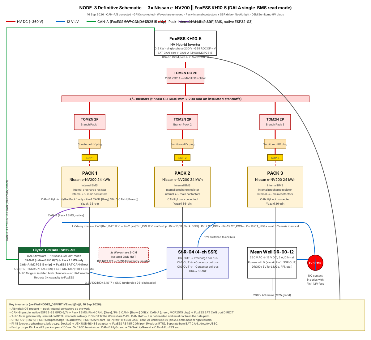
Full HV + LV topology: TOMZN master/branch breakers, Service Disconnect Plugs, 3× Nissan e-NV200 packs in parallel, FoxESS KH10.5. For the LV-only control/comms wiring in isolation, use the tab above.
Full HV + LV topology: TOMZN master/branch breakers, Service Disconnect Plugs, 3× Nissan e-NV200 packs in parallel, FoxESS KH10.5. For the LV-only control/comms wiring in isolation, use the tab above.
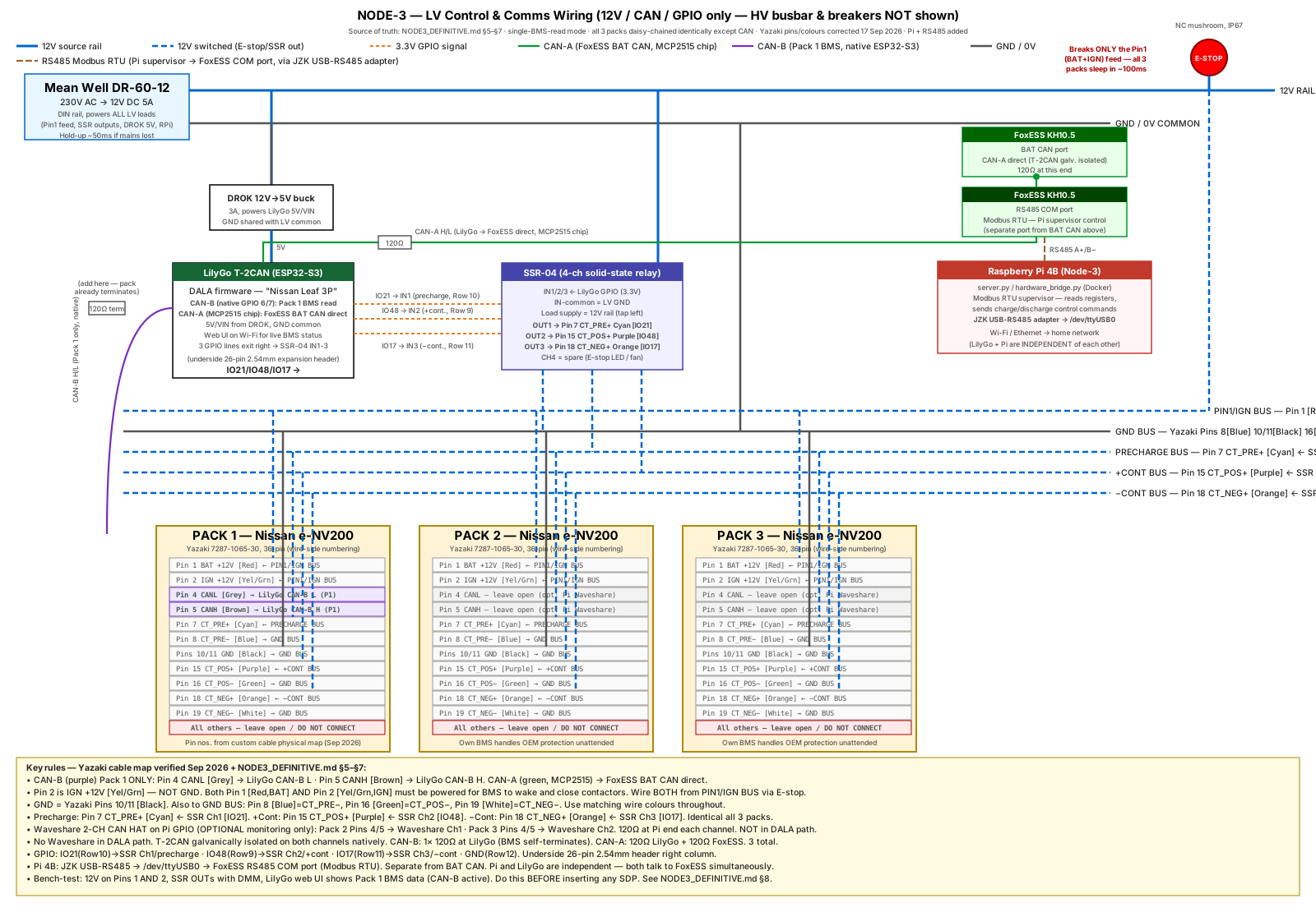
12V rail, E-stop, LilyGo T-2CAN, SSR-04, CAN-A/CAN-B and the Yazaki daisy chain only — HV busbar/breakers deliberately omitted here for clarity. See "Connection Tables" tab for the pin-by-pin wiring list.
All pins below wired identically on all 3 packs (daisy-chain) except CAN (Pin 4/5) which is Pack 1 only. Pin nos. verified from physical custom cable map Sep 2026. Pin 2 is IGN +12V — NOT GND.
| Pin | Signal | Pack 1 | Pack 2 | Pack 3 |
|---|---|---|---|---|
| 1 | BAT +12V [Red] | ✅ PIN1/IGN BUS via E-stop + 1A fuse | ✅ same bus (daisy) | ✅ same bus (daisy) |
| 2 | IGN +12V [Yel/Grn] | ✅ PIN1/IGN BUS (same as Pin 1, via E-stop) — NOT GND | ✅ same bus (daisy) | ✅ same bus (daisy) |
| 4 | CANL [Grey] | ✅ to LilyGo CAN-B L (native ESP32-S3) | ❌ leave open (opt: Pi Waveshare Ch1) | ❌ leave open (opt: Pi Waveshare Ch2) |
| 5 | CANH [Brown] | ✅ to LilyGo CAN-B H (native ESP32-S3) | ❌ leave open | ❌ leave open |
| 7 | CT_PRE+ [Cyan] | ✅ ← SSR-04 OUT1 [IO21] — all 3 packs (daisy) | ||
| 8 | CT_PRE− [Blue] | ✅ → GND BUS — all 3 packs (daisy) | ||
| 10/11 | GND [Black] | ✅ → GND BUS — all 3 packs (daisy) | ||
| 15 | CT_POS+ [Purple] | ✅ ← SSR-04 OUT2 [IO48] — all 3 packs (daisy) | ||
| 16 | CT_POS− [Green] | ✅ → GND BUS — all 3 packs (daisy) | ||
| 18 | CT_NEG+ [Orange] | ✅ ← SSR-04 OUT3 [IO17] — all 3 packs (daisy) | ||
| 19 | CT_NEG− [White] | ✅ → GND BUS — all 3 packs (daisy) | ||
| all others | Cell taps + NTCs | 🚫 DO NOT CONNECT — leave isolated in heatshrink, label "do not touch" | ||
Pins 4/5 CAN: Pack 1 → LilyGo CAN-B H/L. Packs 2/3: optionally connect to Pi Waveshare 2-CH CAN HAT (monitoring only, NOT in DALA path). Fit 120Ω terminator at LilyGo end of CAN-B (pack self-terminates). Waveshare channels: 120Ω at Pi end. SSR coil polarity: CT_PRE+/CT_POS+/CT_NEG+ receive switched 12V from SSR OUT; CT_PRE−/CT_POS−/CT_NEG− go to GND. Source: physical custom cable map, Sep 2026.
| GPIO / pin | Role | Wired to |
|---|---|---|
| IO21 (row 10) | Precharge SSR drive (3.3V) | SSR-04 channel 1 IN+ — underside 26-pin header R.col |
| IO48 (row 9) | +Contactor SSR drive (3.3V) | SSR-04 channel 2 IN+ — underside 26-pin header R.col |
| IO17 (row 11) | −Contactor SSR drive (3.3V) | SSR-04 channel 3 IN+ — underside 26-pin header R.col |
| GND (row 12) | Common return | SSR-04 IN− common — underside 26-pin header R.col |
| CAN-B (native GPIO 6/7) | Pack 1 BMS read | Yazaki Pack 1: Pin 4 CANL [Grey] / Pin 5 CANH [Brown] |
| CAN-A (MCP2515 chip) | FoxESS BAT CAN comms | FoxESS KH10.5 BAT CAN port — DIRECT (T-2CAN galv. isolated, no external HAT needed) |
| 5V / VIN | Module power | DROK 12V→5V buck output |
CAN-B (native ESP32-S3, GPIO 6/7) reads Pack 1 BMS. CAN-A (MCP2515 chip) talks to FoxESS BAT CAN — wired DIRECT, no external isolator. Both channels are galvanically isolated on-board. Add 120Ω across CAN-B H/L at the LilyGo end (pack self-terminates at BMS). Add 120Ω at LilyGo end AND FoxESS end of CAN-A (3 resistors total). Waveshare 2-CH CAN HAT: do NOT put it in the DALA/LilyGo signal path. It CAN be used on the Pi GPIO header to monitor Packs 2/3 CAN independently (Pack 2 Pins 4/5 → Waveshare Ch1; Pack 3 Pins 4/5 → Waveshare Ch2; 120Ω at Pi end each channel) — optionally, for monitoring only.
| Channel | IN− | IN+ from LilyGo | OUT (switches 12V to coil) |
|---|---|---|---|
| 1 | GND | IO21 (row 10) | Pin 7 CT_PRE+ [Cyan] / Pin 8 CT_PRE− [Blue]→GND — all 3 Yazakis (daisy) |
| 2 | GND | IO48 (row 9) | Pin 15 CT_POS+ [Purple] / Pin 16 CT_POS− [Green]→GND — all 3 Yazakis (daisy) |
| 3 | GND | IO17 (row 11) | Pin 18 CT_NEG+ [Orange] / Pin 19 CT_NEG− [White]→GND — all 3 Yazakis (daisy) |
| 4 | — | — | Spare (E-stop status LED / fan) |
SSR-04 has NO shared OUT−. Each channel is a relay contact: terminal A = 12V+ from WAGO, terminal B = coil+ (Cyan/Purple/Orange wire). Coil− (Blue/Green/White wires, Yazaki Pins 8/16/19) go direct to GND bus — they do NOT pass through the SSR. IN− is shared across channels, goes to LilyGo GND. Sequence (driven by LilyGo firmware): precharge ON → wait → +cont ON → −cont ON → precharge OFF.
| Fault | What happens |
|---|---|
| Single cell overvoltage in any pack | That pack's own BMS opens its internal contactors. Other 2 packs stay live. In single-BMS-read mode, LilyGo won't directly see a Pack 2/3 fault — relies on that pack's own protection. |
| LilyGo crash / firmware fault | SSR drive signals go LOW → coil voltage drops → all contactors open. Failsafe by design. |
| 12V rail loss | Pin 1 [Red,BAT] + Pin 2 [Yel/Grn,IGN] drop → BMSes go to sleep → contactors open. |
| Mains AC loss | DR-60-12 has ~50ms hold-up, then 12V drops, then contactors open. Whole bus dies safely. |
| Person needs to disconnect NOW | E-stop — drops Pin 1 [Red,BAT] AND Pin 2 [Yel/Grn,IGN] across all 3 packs simultaneously, ~100ms. Both must drop — cutting only one leaves BMSes partially powered. |
| Service work | Pull Service Disconnect Plugs (with HV gloves). Each SDP physically breaks the cell string. |
| Branch fault on one pack | That pack's TOMZN branch breaker trips. Other 2 carry on. |
| Inverter fault | Master TOMZN trips manually, or FoxESS opens its internal DC contactor. |
Full pre-energise checklist and 14-step commissioning sequence: see NODE3_DEFINITIVE.md §8 in this folder. Do not energise to grid until G99 export approval is confirmed.